Les broches analogiques peuvent être traitées comme des broches digitales


UNO R4 WIFI :


Différence entre la carte Arduino Uno R3 et R4 : Une plus grande mémoire et une vitesse d’horloge améliorée : 16 fois plus de mémoire et une vitesse d’horloge trois fois plus rapide pur l’UNO R4.
R4 dispose également d’un connecteur USB-C, d’un RTC (module temps réel) exemple ici, d’un véritable canal DAC (exemple pour de la musique) et d’une prise en charge du protocole CAN (solution de qualité industrielle pour connecter plusieurs périphériques à l’aide d’un simple bus, comme dans les voitures, les machines ou les robots. UNO R4 prend en charge le protocole complet de manière native, seul l’adaptateur de couche physique est nécessaire). La version WiFi de R4 dispose d’une matrice LED 12 × 8 intégrée supplémentaire et d’un connecteur Qwiic

Prise en charge de l’horloge RTC alimenté par une batterie externe
La carte Arduino UNO R4 Wifi possède deux broches supplémentaires qui permettent le comportement suivant :
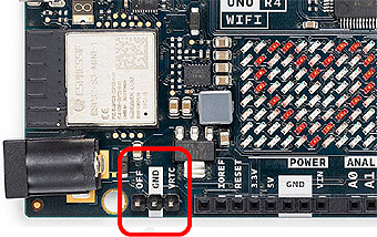
➔ Broche « OFF »: éteint la carte
➔ Broche « VRTC » : garde l’horloge interne en temps réel alimentée et en marche (à utiliser avec une batterie externe de 1.6 à 3.6 V.
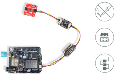
Nœuds Qwiic = expérience plug-and-play
L’Arduino UNO R4 WiFi dispose d’un connecteur au standard Qwiic I2C qui permet aux utilisateurs de connecter un ou plusieurs nœuds choisis parmi l’immense écosystème Qwiic déjà disponible sur le marché.
Emulation de souris clavier : https://docs.arduino.cc/tutorials/uno-r4-wifi/usb-hid
Pavé de LEDs : https://docs.arduino.cc/tutorials/uno-r4-wifi/led-matrix
| Difference | UNO R3 | UNO R4 |
| Microcontroller | 8-bit ATmega328p | 32-bit Renesas RA4M1 |
| Clock frequency | 16 MHz | 48 MHz |
| Wireless module | NO | *ESP32-S3 Mini |
| Memory | 2KB SRAM, 32KB FLASH, 1KB EEPROM | 256 kB Flash, 32 kB RAM *ESP: 384 kB ROM, 512 kB SRAM |
| RTC | NO | YES |
| Input voltage (VIN) | 6-20 V | 6-24 V |
| Digital I/O pins | 14 | |
| Analog input pins | 6(10-bit) | 6(14-bit) |
| PWM pins | 6(8-bit) | 6(12-bit) |
| DAC pin | NO | 1(12-bit) |
| CAN Bus | NO | 1 |
| Dimensions | 68.58 x 53.44 mm | 68.6 x 53.4 mm |
Exemple de connexion WIFI avec la librairie WiFiS3.h à une API NodeJs
/*
This example show how to call a NodeJs API with Data
*/
#include "WiFiS3.h"

const char* ssid = "xxxx";  // SSID
const char* pass = "yyyy";  // your network password

char server[] = "192.168.0.23";//-- Warning the ip of the machine / server
int port = 3000;               // Port of your Node.js API

WiFiClient client;

void setup() {
  Serial.begin(9600);

  // Attempt to connect to WiFi network
  while (WiFi.begin(ssid, pass) != WL_CONNECTED) {
    Serial.println("Attempting to connect to WiFi...");
    delay(1000);
  }

  Serial.println("Connected to WiFi");
  printWifiStatus();
 client.stop();
  if (client.connect(server, port)) {
    // Construct the request body
    String postData = "{\"temperature\": 25.8, \"humidity\": 51.2}";
    //--> curl -X POST -H "Content-Type: application/json" -d '{"temperature": 25.2, "humidity": 50.8}'
    // Make a HTTP POST request
    client.println("POST /data HTTP/1.1");
    client.println("Host: " + String(server));
    client.println("Content-Type: application/json");

    client.print("Content-Length: ");
    client.println(postData.length());
    client.println();
    client.println(postData);
    client.println("Connection: close");
    client.println();

    Serial.println("Request sent");
  } else {
    Serial.println("Connection failed");
  }
}
/* -------------------------------------------------------------------------- */
void loop() {
  /* -------------------------------------------------------------------------- */
  read_response();
  // if the server's disconnected, stop the client:
  if (!client.connected()) {
    Serial.println();
    Serial.println("disconnecting from server.");
    client.stop();

    // do nothing forevermore:
    while (true)
      ;
  }
}
/* ---------------------------------------------------------------------- */
void read_response() {
  /* -------------------------------------------------------------------- */
  uint32_t received_data_num = 0;
  while (client.available()) {
    /* actual data reception */
    char c = client.read();
    /* print data to serial port */
    Serial.print(c);
    /* wrap data to 80 columns*/
    received_data_num++;
    if (received_data_num % 80 == 0) {
      Serial.println();
    }
  }
}
/* ------------------------------------------------------------------ */
void printWifiStatus() {
  /* --------------------------------------------------------------- */
  // print the SSID of the network you're attached to:
  Serial.print("SSID: ");
  Serial.println(WiFi.SSID());

  // print your board's IP address:
  IPAddress ip = WiFi.localIP();
  Serial.print("IP Address: ");
  Serial.println(ip);

  // print the received signal strength:
  long rssi = WiFi.RSSI();
  Serial.print("signal strength (RSSI):");
  Serial.print(rssi);
  Serial.println(" dBm");
}
NodeJs API :
const express = require('express');
const bodyParser = require('body-parser');
const { Pool } = require('pg');

const app = express();
const port = 3000;

// PostgreSQL connection configuration
const pool = new Pool({
  user: 'postgres',
  host: 'localhost',
  database: 'dbmeteo',
  password: 'xxx',
  port: 5432,
});

// Middleware to parse JSON bodies
app.use(bodyParser.json());

// API endpoint to receive temperature and humidity data
app.post('/data', async (req, res) => {
  const { temperature, humidity } = req.body;

  try {
    // Insert data into the database
    const result = await pool.query('INSERT INTO sensor_data (temperature, humidity, timestamp) VALUES ($1, $2, NOW())', [temperature, humidity]);

    res.status(201).send('Data stored successfully');
  } catch (error) {
    console.error('Error storing data:', error);
    res.status(500).send('Error storing data');
  }
});

// Start the server
app.listen(port, () => {
  console.log(`Server running on port ${port}`);
});
Base de données Postgres :
CREATE TABLE sensor_data (
    id SERIAL PRIMARY KEY,
    temperature NUMERIC NOT NULL,
    humidity NUMERIC NOT NULL,
    timestamp TIMESTAMP DEFAULT CURRENT_TIMESTAMP
);
Autre exemple :
Digispark Tiny85 Micro Usb
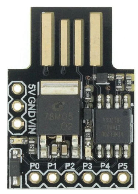
Here is best video explaining how to make it work https://www.youtube.com/watch?v=MmDBvgrYGZs and here is link to drivers https://github.com/digistump/DigistumpArduino/releases. LED is connected to pin 1 (D0) As there is no serial port board have to be unplugged and plugged before programming (there is message in console to plug in board).
http://digistump.com/wiki/digispark/tutorials/connecting
Pour windows, 1°) ajouter la carte en ajoutant l’URL des cartes dans l’interface Arduino avec l’adresse :
-
In the box labeled “Additional Boards Manager URLs” enter:
http://digistumpcom/package_digistump_index.json
and click OK
Puis
-
Go to the “Tools” menu and then the “Board” submenu – select “Boards Manager” and then from the type drop down select “Contributed”:
-
Select the “Digistump AVR Boards” package and click the “Install” button.
Pour le driver entrez dans une fenêtre système :
D:\Profile\xxx>D:\Profile\xxx\AppData\Local\Arduino15\packages\digistump\tools\micronucleus\2.0a4\post_install.bat
UNO :
La tension d’alimentation externe conseillée va de 7v à 12v point central positif si la prise jack est utilisée, sinon le + sera connecté sur la broche Vin et le – sur la broche GND.


Pour la carte 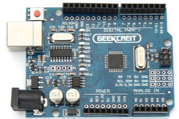 Geekcreit® UNO R3 ATmega328P
Le driver a installer avant de brancher la carte est téléchargeable ici
MEGA 2560 :http://www.electroschematics.com/7965/arduino-mega-adk-pinout/


Serial: 0 (RX) and 1 (TX);
Serial 1: 19 (RX) and 18 (TX);
Serial 2: 17 (RX) and 16 (TX);
Serial 3: 15 (RX) and 14 (TX).
Used to receive (RX) and transmit (TX) TTL serial data. Pins 0 and 1 are also connected to the corresponding pins of the ATmega8U2 USB-to-TTL Serial chip.
External Interrupts: 2 (interrupt 0), 3 (interrupt 1), 18 (interrupt 5), 19 (interrupt 4), 20 (interrupt 3), and 21 (interrupt 2). These pins can be configured to trigger an interrupt on a low value, a rising or falling edge, or a change in value. See the attachInterrupt() function for details.
PWM: 2 to 13 and 44 to 46. Provide 8-bit PWM output with the analogWrite() function.
SPI: 50 (MISO), 51 (MOSI), 52 (SCK), 53 (SS). These pins support SPI communication using the SPI library. The SPI pins are also broken out on the ICSP header, which is physically compatible with the Uno, Duemilanove and Diecimila.
USB Host: MAX3421E. The MAX3421E comunicate with Arduino with the SPI bus. So it uses the following pins:
Digital: 7 (RST), 50 (MISO), 51 (MOSI), 52 (SCK).
NB: Please do not use Digital pin 7 as input or output because is used in the comunication with MAX3421E
Non broken out on headers: PJ3 (GP_MAX), PJ6 (INT_MAX), PH7 (SS).
LED: 13. There is a built-in LED connected to digital pin 13. When the pin is HIGH value, the LED is on, when the pin is LOW, it’s off.
TWI: 20 (SDA) and 21 (SCL). Support TWI communication using the Wire library. Note that these pins are not in the same location as the TWI pins on the Duemilanove or Diecimila.
The ADK has 16 analog inputs, each of which provide 10 bits of resolution (i.e. 1024 different values). By default they measure from ground to 5 volts, though is it possible to change the upper end of their range using the AREF pin and analogReference() function.
There are a couple of other pins on the board:
AREF. Reference voltage for the analog inputs. Used with analogReference().
Reset. Bring this line LOW to reset the microcontroller. Typically used to add a reset button to shields which block the one on the board.
NANO :

Si la carte n’est pas reconnue essayez avec les drivers CH341(d’abord Uninstall puis Install) ou FTDI
BEETLE :
Carte Leonardo miniaturisée

Laisser un commentaire